
The IEC 61508 functional safety standard has made life much easier for machine-builders, as well as for end-users. The result has been safer, smarter, smaller, simpler and better-performing machines.
Machine safety has evolved significantly since the 1990s, with the release of the functional safety standard IEC 61508 in 1998 marking a turning point for machine-builders and end-users. With a standardized safety concept, equipment suppliers and machine builders could instill confidence in their customers that their safety systems had been tested and vetted rigorously, and users no longer had to spend time and resources analyzing the risk of a machine or system failure.
The introduction of functional safety and the related standards has also (almost) freed machine builders from the task of safety designing, as well as the need to purchase, install, and connect banks of hardware – such as safety contactors, relays, switches, IOs, and brake controllers – as well the exhausting process of machine safety assessments and approval processes.
Previously, safe machine operation was achieved using relays that cut power if a safety condition was violated – such as an operator entering an enclosure or breaking a light curtain. Functional safety has replaced hardware and the costly approvals process by software. The result is not only truly “functional” safety, but also increased uptime, better productivity, and reduced scrap for end-users.
Unlike traditional hardware-based safety systems, functional safety relies on safety-rated components. The main difference is that instead of using lots of safety components, much of it can be integrated into a servo drive, for example. The ultimate goal is to replace most of the safety hardware with software such as Failsafe over EtherCat (FSoE). Some hardware is still needed – such as safety brakes, IO, and encoders – to control the operating parameters of the equipment.
Rather than cutting power instantly to an axis if a safety parameter is violated, functional safety systems restrict the motion of the axis. This allows the system to handle a fault while maintaining a predefined safety level and informing the user through self-diagnosis and automated alerts.
Monitor and respond
Drive-based safety functions cover a wide range of tasks, from safely stopping the drive, to monitoring motion parameters such as speed, position, or torque. Safety functions integrated into some servo drives include:
- Safe Torque Off (STO). This removes power to the motor. The shaft continues to freewheel without applying any torque until the kinetic energy runs down. The drive remains energized for faster restart. STO can be activated either by two hardware signals or by FSoE communication.
- Safe Stop 1 (SS1). Active braking brings the shaft to a rapid, controlled stop so that the axis stops turning. At this point, STO is invoked. SS1 is used where the motion of an axis could endanger people or equipment.
- Safe Operating Stop (SOS). The drive holds the motor at zero speed without removing torque. Equipment can restart immediately without a reset.
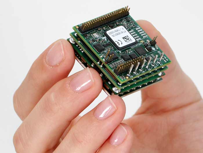
Elmo’s Platinum servo drives incorporate comprehensive safety functions while reducing the number of safety components needed, as well as power consumption, complexity, and machine costs.
Safe Stop 2 (SS2). Controlled braking brings high-kinetic-energy equipment to a controlled stop, at which point, SOS is invoked. It is used when additional motion could be hazardous for people, products or equipment.
- Safe Brake Control (SBC). This provides safe control of an external power-off brake, and is generally used on vertical axes. If a redundant braking system fails, the drive typically invokes SOS.
- Safely Limited Speed (SLS). This sets a maximum speed. If a fault causes the system to exceed a threshold value, the drive brings the axis to a safe state.
- Safely Limited Torque (SLT). This restricts motor torque by limiting the current supplied by the drive.
- Safely Limited Position (SLP). This limits the envelope within which a load can move by monitoring its position via encoder feedback. If this reports the load has moved beyond the allowed envelope, it is stopped using SS1/STO or SS2/SOS. The rapid response of these functions minimizes the margin of safety around the equipment.
- Safe Input/Output. For servo drives with Safe I/O (such as Elmo’s Platinum series), two types of digital safe inputs are supported – digital input with test pulse output for diagnostics, and digital input with OSSD (output signal switching device) for light barriers, light curtains and so on. The safe brake output is to SIL3. Safe input logic is similar to FSoE control, and safe output logic is similar to FSoE status.
Functional safety requires a communications network based on a safety-rated protocol, which includes self-checking. If it detects corrupted data or a communication fault, the axis will fail to a known safe state. FSoE uses a TÜV -certified safety network and is especially beneficial in applications such as robots, because it needs only one cable for safety, minimizing the amount of space required inside the robot arm.