The nature of servo operation requires specific characteristics of the power source. In most cases, the source is an AC line, single or three phases, “direct to the mains,” or via an isolation transformer.
Servo operation requires a voltage source that is reliable, simple and most importantly one that is able to deliver “momentary” high power demands and that “conducts” power from and to the motor (4 quadrants).
In addition, the power supply must withstand a “hostile” operating environment such as: voltage instabilities, high spikes, transients, bursts, EMI, high mechanical vibrations and mechanical shocks, extreme temperature, and high humidity.
The power consumption behavior of a servo application contains many accelerations and declarations that require momentary high power peaks, while the average power required is significantly lower.
The Power Supply has two major “functional servo” tasks:
1. To supply the DC bus voltage required to power the servo drives.
2. To “absorb” the regenerating/braking power from the motor and the mechanical load.
Functionalities of Servo Power Supply
- Create the DC bus source designed to meet the voltage required to fulfill the servo system needs
- Be able to deliver sufficient power to drive the momentary peaks and averages of the mechanical loads
- Have reasonable voltage stability. No need for a regulated or stabilized DC bus ─ the only concern should be satisfying the minimum voltage requirements to achieve the required speed and torque.
- Limited and controlled voltage variations. Ensure that the maximum voltage limits of the servo drives will not be exceeded.
- Bi-directional energy flow. In servo operation it is essential that the power supply will be able to deliver power to the load and absorb power from the load.
- High frequency power handling. The servo drives’ operation creates PWM high frequency currents flowing on the DC bus. These currents must be absorbed and properly filtered by the power supply.
Environmental requirements:
- Safety standards
- EMC, immunity and emission
- Inrush current control
- Meeting environmental requirements (vibrations, temperature, humidity, etc.)
To fulfill the above the Power Supply for servos requires:
- Rectifying the AC voltage input into DC bus voltage.
- bi-directional “Energy Reservoir” for continuous and instant peak power demands from the servo system.
- A shunt regulator for absorbing energy from the load in case of regeneration or braking.
- An inrush current limiter.
- A high-frequency current ripple “swallower.”
- Filtering EMI from and to the servo drives.
- Line voltage transient protection.
- Safety.

There are two basic topologies to power servo drives when operating from an AC source/network.
1. A Shared DC Power Bus
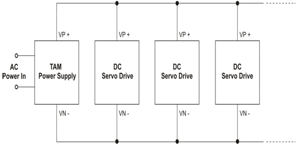
One power supply runs multiple servo drives sharing one DC bus.
2. An AC Common Power Bus
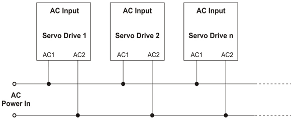
In the AC Common Power Bus, each servo drive has its own, separate power supply.
Resource sharing
The power consumption behavior of a servo application contains many accelerations and declarations that require momentary high power peaks, while the average power required is significantly lower.
In the AC Common Power Bus, each servo drive’s power supply section must be designed to deliver the full peak power requirements resulting in a much greater power supply that is exposed to higher electrical stress. While with the Shared DC Power Bus the total instantaneous (peak) power consumption is much lower, the available power resources for each servo drive is much higher and the overall consumption is lower.
Regeneration “Sharing”
A significant advantage of the Shared DC is the shared shunt regulator. Servo operation is characterized by very short and sharp braking or fast direction changes. As it is rare that all drives are regenerating energy back to the DC bus simultaneously, one shared shunt regulator can serve a few servo drives at the same time. With the AC Common, each drive has its own shunt regulator that must be powerful enough to absorb its motors energy regeneration on its own.
Safety, Protections, EMI, etc
Safety regulations require that each load connected to the mains must have mandatory safety capacities such as a circuit breaker, contactor, etc.
Safety, Contactors, Circuit Breaker
- In the Shared DC, only one set of contactors, circuit breakers, etc. are required.
- In the AC Common, each drive must have an independent EMI filtering network.
EMI
- In the DC Shared, one EMI network in the power supply serves all the drives.
- In the AC Common, each drive must have an independent EMI filtering network.
Leakage Current
- In the DC Shared, significant leakage only occurs in the power supply (the leakage is usually created by the EMI filtering network).
- In the AC Common, each drive has significant current leakage, and thus the total leakage is much higher.
Inrush Currents Limits
- In the DC Shared, one set of limiter installed in the power supply serves the multiple servo drives.
- In the AC Common, each drive must be equipped with Inrush Limiters.
Adhering to the above rules results in duplicity of “Safety, Protection & EMI” devices in the AC Shared Power Supply.
Actually, too many AC Common Power Bus implementations ignore the safety regulations, thus exposing the operator and the machine to high risks.
One AC input to multiple servo drives, one safety set of contactor + circuit breaker, one EMI filtering network, one common current leakage source, one powerful shunt regulator, one DC bus shared by multiple servo drives:
Shared DC Power Bus
Simple Schematics of an AC Common
Multiple AC inputs, multiple safety sets of contactors + circuit breakers, multiple EMI filtering networks, multiple current leakage sources, multiple powerful shunt regulators, multiple and individual DC buses.

AC Common Power Bus

Why DC Shared?
- Sharing the DC bus results in a more powerful DC source for each drive
- More efficient and practical regeneration
- Saves 5% -8% of the power consumption
- Reduces the amount of “external” mandatory components
- Reduces space (for > 2 axes applications)
- Reduces heat dissipation
- Reduces “stress” from the AC network
- Reduces overall costs (for > 2 axes applications)
Typical “Shared” DC Bus Application:3XGTRO+1XTAM

Nevertheless, the “AC Common” is very common, because:
The AC Common is simpler to implement. Each drive is independently powered. The DC Shared requires a bit more design considerations for powering the multiple servo drive system.
How many drives can be powered by a single power supply?
A typical mistake is counting by currents:
Σ Motor Current = Current of the Power supply
In servo applications, the current on the DC bus is usually significantly lower than the current to the motor.
Go by the power:
The Output Power of a power supply = VAC*√2
Example:
Power Supply
- Output Power of Power Supply = 20A cont., 40A peak.
- Input to Power Supply= 230VAC.
- Output Power of Power Supply = 230*√2*20 ≈ 6500W
Servo Motor
- Nominal Torque = 4.77NM
- Nominal speed = 3000 RPM
- Power output of the motor ≈ 4.77 * 3000/ 10 ≈ 1400W
How many “1400W” drives on a “6500W” supply?
6500/1400 = 4.6
As a rule of thumb, 5 or even 6 “1400W” drives can be powered by a single “6500W” supply.
The “6500W” supply can easily deliver peak power of “2* 6500W.”
A few words on Powering Servos from a “single phase”
- In most (all) of the cases, the “single phase” is Phase-Neutral (120VAC, 230VAC)
- The “Neutral/ZERO Line” is “intended” to carry ZERO current. It is a type of SOFT (high-impedance) power line.
- The Electricity Network “assumes” that “somewhere” along the AC lines the 3-phases are balanced and no current flows on the ZERO Line.
- As a rule of thumb, the ZERO line can carry up to 15% of the Current rating of phases.
Single phase loading might cause unbalanced voltages relative to the ZERO Line.
This might cause “single phase” voltage transients, spikes, surges, sags, etc.
This is true to all devices that are connected to the ZERO line.
Some devices might be exposed to too high voltages, others to too low voltages.
In extreme cases, the “single phase” device might fail.
This has occurred in China and also in Switzerland.
But, single phase is very popular and also cost effective, how can one use it safely?
If an application is powered from a single phase source ensure that:
- the ZERO line will not conduct more that 35A- 40A
- the ZERO line must be properly sized in the site and in the machine
- the ZERO Line must be properly grounded (PE) at the site’s AC Power inlet
- all devices with the Zero line connected to the chassis/ground/PE, are “well” shorted to each other

For a “High Power” single phase application the connections diagram could be employed, however, loading must then be balanced loading (ZERO Line current < 15%)
In servo applications, power consumption balancing is not very practical.

In some applications that exercised the above topology, balanced loading could not be guaranteed; therefore “230VAC” fluctuations exceeded peaks of even 300VAC. In extreme cases, the unbalancing caused failures.
Voltage Ripple
- The 3-phases have an inherent voltage ripple of approx. 15% W/O any capacitance.
- The single phase has an inherent ripple of 100% W/O capacitance.
The 3-phase voltage is much more rigid and the DC bus is not sensitive to loading.

Single-phase
The stress on the rectifier is much lower with 3-phases

Three-phase
To create an adequate DC bus the single phase requires a “huge” amount of capacitance.
- This is seldom enough to fulfill the requirements of the necessary power of a dynamic mechanical load
- This increases the stress (RMS) and the heat dissipation of the bridge devices (requires higher rating devices)
- This causes pollution (EMI) on the AC Lines
- And still there are high voltage sags
While the 3 phases:
- Require very low capacitance mainly required to handle the high frequency PWM currents
- The stress on the rectifiers is significantly lower
- Voltage Saga are no more than 15%
- The AC lines stress and EMI is significantly lower
So, why not always use 3-phases?
In most countries “3 phases” is 3X400VAC or even 3X480VAC
- From a servo performance point of view, it is not always beneficial to operate at such high voltages
- The 400VAC drives and motors are not as popular as the 230VAC and therefore the cost is significantly higher and the variety lower
- It is more difficulty to comply to safety standards at such high voltages
- Some applications are restricted to single phase operation (MRI)
In the U.S. and Japan there is 3X230 that benefits both: 3-phases and 230VAC
Conclusions:
The 3-phases is by all means a better technical solution
The single phase is much “simpler” and cost effective
There are 2 basic topologies:
- Direct to the Mains connection. No Isolation transformer
- Power input is Isolated from the Mains via an isolation transformer or SMPS
Elmo’s high voltage servo drives and Tambourine power supplies series are designed to be directly connected to the mains without an Isolation transformer.
The low-voltage servo drives require isolation from the mains.
Elmo defines:
- Low Voltage Servo Drive when VDC_BUS ≤ 200VDC
- High Voltage Servo Drives when VDC_BUS ≥ 400VDC
The power switching devices in the low voltage servo drives are MOSFETs, while IGBTs are in the high voltage servo drives.
The main advantages of the “direct to the mains” are:
- No need for isolation transformer.
- The electrical installation is much simpler.
Advantages of Low Voltage Servo Drives:
- Better servo performance
- Higher PWM frequency. Results in wider bandwidths, lower current ripple.
- Faster switching transitions resulting in better linearity, wider bandwidth, fewer losses, higher output voltage
- Lower “conduction” voltage resulting in fewer losses, higher output voltage, better linearity
- Significantly Less EMI
- Significantly higher efficiency
- Incomparably smaller size!
- Much Easier to comply to Safety STDs
- Lower costs
The only disadvantage of low voltage is the need for the isolation transformer.
With Elmo
- In the high voltage servo drives, the control section is isolated from the power section.
- In most of the low voltage servo drives, the Common of the control section is internally connected to the Power Return (Common of the DC power).
Working with low voltage drives (non-isolated) requires a DC Bus Power Supply that is isolated from the mains.
The main disadvantage of low voltage is the need for a transformer.
This diagram displays the simplest “Ready-to-use” power supply

- “Ready-to-use” AC Input Isolated low voltage DC source.
- No need for bulky, heavy transformer that requires installation
- Simple installation
- Small size
- “Fully” protected
- Reasonable & “competitive” cost
However…
SMPS are designed only to “deliver” power out to a passive load.
No ability for absorbing regenerating power from the Drive-Motor (Servo). When regenerating, the SMPS might be damaged!
SMPS are very sensitive to Inductive loads that “typically” create spikes, transients, surge voltage. In extreme cases the SMPS might be damaged!
The voltage regulation might be a disadvantage when regenerating. In regeneration/ braking, the load transfers power back to the power supply “enforcing” voltage increase on the terminals of the SMPS. When the terminal voltage exceeds the “set Voltage” of the SMPS, the close loop might fall “out of loop.” The recovery might last too long and at this point there is no output voltage from the SMPS. “No Power, No Servo!”
No peak current/ power capability.
The SMPS is designed to deliver continuously the rated power. It can’t deliver peak currents that are crucial for Servo operation.

The “Start” seems to be very simple…
However, eventually it is “not so simple”… Series full power diode ( block regeneration), anti- parallel diode (protect from inductive load spikes), external additional capacitance (to absorb at least some of the negative currents pumped from the motor) And still no peak capability, nor braking capability.
Attention must be paid to some (too many) of the “low cost” SMPS:

- “Ancient” electronics (that indicate a “low-tech” product)
- ”Poor” workmanship
- Quality of Components? “God Knows”
- Not suitable for industrial environment
- Be aware of the quality & reliability. There might be issues in the future!
- And those SMPSs that are a little better, cost much more…
Conclusions:
- For applications that require an SMPS of up to 300W – 400W, there is a very good chance that the SMPS will be a better choice!
- Lots of attention must be paid to the quality of the SMPS
Two critical cases to distinguish:
- Power Supply that is connected “Direct to the Mains”
- Power Supply that is isolated from the “Mains”
Simplified Connections Diagram of “Direct to Mains” and “Isolated Mains”

Attention must be paid to the differences between PR to Vn-.
Both are the most negative voltage of the rectifying bridge.
In the “Isolated Mains” connection, the PR is connected to the Earth and Systems Returns (Grounds)

In the “Direct to Mains” connections, the Vn- must not be connected to Earth, Grounds, or Returns. Any such connection will cause destructive failure.

- The TAM is Elmo’s series of Power Supplies designed for servo applications.
- The TAM series meets all the requirements discussed in this article.
TAM-20/XXXVAC is a compact “Direct to Mains” Power Supply for Servo Applications Up to 505VAC

The TAM is Elmo’s series of Power Supplies designed for servo applications.
The TAM series meets all the requirements discussed in this article.
Capabilities:
|
Power Supply |
TAM-20/36VAC |
TAM-20/60VAC |
TAM-20/120VAC |
TAM-20/230VAC |
TAM-20/460VAC |
|---|---|---|---|---|---|
| Nominal Input AC Voltage |
1X36VAC |
1X60VAC |
1X120VAC |
1X230VAC |
1X460VAC |
| Line Frequency |
40 – 70 Hz |
40 – 70 Hz |
40 – 70 Hz |
40 – 70 Hz |
40 – 70 Hz |
| Max Input AC Voltage |
1X40VAC (L-N) |
1X63VAC (L-N) |
1X134VAC (L-N) |
1X270VAC (L-N) |
1X505VAC (L-N) |
| Max Output Power Cont. |
1100W |
1800W |
3800W |
7600W |
14000W |
| Max Output Power Peak |
2200W |
3600W |
7600W |
15200W |
28000W |
| Nominal DC bus Output (at nominal AC Voltage) |
50VDC |
85VDC |
170VDC |
325VDC |
560VDC (for 400VAC) |
| Shunt Power (Peak) |
1.8KW |
4.5KW |
5.5KW |
6KW |
6.3KW |
| DC Output Cont. Current |
20A |
20A |
20A |
20A |
20A |
| DC Output Peak Current |
40A |
40A |
40A |
40A |
40A |
| Mating Drives |
XXX-YY/60 |
XXX-YY/100 |
XXX-YY/200 |
XXX-YY/400 |
XXX-YY/800 |
| Weight |
1155 gr |
1155 gr |
1155 gr |
1155 gr |
1155 gr |
Size example:
Operating Voltage: 230VAC
Example: Motors nominal power:
- Motor1 = 2500W
- Motor2 = 1500W
- Motor3 = motor4 = motor5 = motor6 = 800W
- ΣMotors Watt= 7200W
Is it okay to supply 7200W from TAM-20/230VAC?
- The output power of the TAM at 230VAC is “only” 6500W?
Yes, it is okay.
As a rule of thumb:
In a multi-axis application the ΣWatts of the motors can be “TAM Output Power at Nominal Voltage” +20%.
What kind of cables?
AC inputs:
- Sufficient: STD Electrical Cable, bundled
- Recommended : For better EMC, use shielded & bundled
Cables DC outputs:
- Sufficient: STD Electrical
- Recommended (highly): To meet EMC, use shielded & bundled cables, which is almost mandatory
Why needed?
- Increase the current output capability
- Increase the shunt power absorption capability
Paralleling 2 x TAM20/XXXVAC
- With 3-phase input voltage, the output current is doubled to:
TAM20+TAM20=TAM40 (3 phase input).
- With a single phase input voltage
TAM20+TAM20=TAM32 =32A (1-phase input)
SHUNT, The Shunt Power absorbing capability is doubled when paralleling two TAMs no matter if it is a single-phase or three- phases
Paralleling 3 x TAM? With some derating It will work, but what for?
The TAM100 is a more economical and efficient solution

The IEC61800 is:
The most comprehensive Safety & EMC standard for “Variable Drives”. Elmo decided to adopt it throughout its product ranges, in addition to the UL and other relevant standards

