
How does your motor work?
Operating mode
A servo motor operates with closed-loop feedback. A servo axis can close the control loop around torque, velocity, position, or some combination thereof depending on the application. Drive modes and axis operating modes are determined by the motion required by the application.
Let’s start with torque mode. Torque is proportional to the motor’s current. The drive amplifies the controller signal so that it supplies the motor with the current that will turn it and generate the torque it is supposed to. The torque mode is ideal for capping axes and punch presses. A torque loop is closed by inductive sensing within motor windings. Analog and digital drives can operate in torque mode.
An encoder, resolver, or Hall-effect sensor on the motor shaft and/or load is needed to provide accurate velocity control for applications like spindles and AGVs. Digital drives can process this data to close the velocity loop. Analog drives can do the same. Because analog drives lack microprocessors, they require analog feedback, like tach generators.
The third operating mode is position mode, which encompasses point-to-point movement as well as highly synchronized positioning. Position mode also requires feedback. Motion controllers close position loops. Depending on the application, digital drives may make more sense to close the position loop. Analog drives cannot close the position loop and need a controller.
Centralized control versus distributed control
Next, driving decisions are dictated by the machine’s overall control architecture. The design followed this architecture for decades: PLC handled machine logic and I/O, while the dedicated motion controller calculated motion trajectories. Modern control architectures have become more flexible. PCs can perform the role of motion controllers. Multi-axis motion can be handled by some PLCs, though highly coordinated motion still requires a motion controller.
Typically, sensitive electronic components, such as controllers and drives, must be incorporated into climate-controlled cabinets with cabling running out to each motor. A centralized architecture decreases reliability and increases maintenance because cabling is the most common point of failure, making connections takes time and leads to error. This leads to more wiring and higher costs. Digital drives offer an alternative.
Some digital drives have sufficient computational capabilities to perform path planning on their own, without a motion controller. They can close the loop on torque, velocity, and position. The architectures of distributed control vary depending in part on the communications bus used but include master-slave and daisy-chain (ring) topologies.
Motor requirements
Electric motors commonly used for automation include synchronous rotary, linear motors (AC and DC), stepper motors, voice-coil motors, and AC induction motors. Although variable-frequency drives (VFDs) can be used with AC induction motors to provide motion control, it is not a part of this blog. We will focus on drives used in synchronous motors and stepper motors.
DC motors can be classified as permanent magnet brushed DC (PMDC) motors or brushless DC (BLDC) motors. Brushed motors use mechanical contacts to communicate with the motor. They are operated as single-phase motors and require only two wires to supply the specified voltage.
BLDC servo motors are generally three-phase motors. They require four wires (one per phase plus ground). As the motor turns in the required direction, the drive energizes the windings in the correct sequence.
Not all analog servo drives are capable of driving BLDC motors, so if your system includes a BLDC motor, be sure to select a drive that has that functionality. Digital drives offer much more flexibility – they are generally capable of driving brushed DC servo motors, BLDC servo motors, and even AC synchronous servo motors. In the latter case, the drive converts AC input into DC output using PWM. Again, this is a specialized functionality, so ensure the drive you choose has this capability.
Stepper motors have different drive requirements than servo motors. Although stepper motors are available in several different designs, the most common devices on the market are two-phase motors. To operate a two-phase stepper motor, the drive needs to have four sets of power FETs. They are connected with four wires (A+ and A-, B+, and B-) and a ground. As a result, a stepper motor can’t be driven by a conventional servo drive.
Although dedicated drives exist for each motor type, there are also hybrid drives that can be used with to power multiple types of motors. In the case of hybrid drives, the drive just needs to be properly wired and configured through the software.
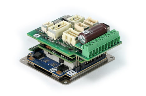
Elmo’s Platinum Bell. Platinum Bell can support, for example, 2 voice coil motors, 1 brushless DC motor, or a 2 phases stepper motor.
Power
Powering the motor is the fundamental function of a drive. To accurately position the load, the drive must deliver the necessary voltage and current to enable the motor to generate torque and speed. Specifying a drive requires considering not just motor parameters and application requirements but also the power source for the drive itself. Optimizing system performance, reliability, and costs requires a nuanced approach.
Specifying output power
A common mistake made by OEMs is to size the motor for the application and then just buy a drive that can run the motor at top speed. This approach not only fails to optimize system performance, but it can also cause error and even premature failure. For very simple systems, running the motor at maximum torque or top speed may be enough but again, it’s important to look at the big picture.
Drives have maximum current specifications, but most are also capable of exceeding peak current for brief intervals. This enables a motor-drive combination to produce bursts of high torque, also known as over-torque or over-current mode. If an axis primarily runs at a lower torque but needs occasional high-torque bursts, it may be possible to buy a smaller, less-expensive drive and use it in over-current mode to provide torque spikes. This technique must be applied with care, however. Most drives can only deliver peak current for a limited time without burning up. If peak torque from the motor requires 10 A from the drive, for example, then running the motor at three or four times peak value requires 30 A or 40 A from the drive. That can become a problem in a hurry. Determine duration and frequency for over torque and consult with your vendor to determine whether you can take advantage of the functionality or whether the drive needs to be upsized.
Input power to the drive
Achieving the desired system performance means providing appropriate input power to the drive. Does the machine have multiple power rails or is it locked into a level due to hardware decisions made for the rest of the machine or facility?
Battery-powered systems require special attention. Performance and maximizing run time per charge are key considerations. After all, a portable system like an automated-guided vehicle (AGV) isn’t very useful if it spends most of its time in the charging bay. Focus on conserving every last milliamp, every last millivolt of input. Conserve power by choosing high-efficiency drives and applying the over-torque techniques when possible to minimize drive size. For applications that involve starts and stops or reversals, consider regenerative drives.
In deceleration, a motor generates excess power. That excess power must be removed. It can be dissipated as heat through a resistor. If you want to harvest the power and cycle it back to the battery, use a regenerative drive. For portable products, regenerative drives provide a major competitive advantage.
As with power density, the smaller and lighter the drive, the smaller and lighter the portable system as a whole, which can also greatly increase cycle time for powered vehicles.
If the system incorporates multiple axes of motion, the battery can supply all drives. This opens up trade-offs between drive size and battery voltage.
Remember, the output characteristics of a battery change over its lifecycle, and a 24-volt battery may deteriorate to 18 V or 12 V, potentially causing drive failure. All drives have a minimum operating voltage. If the battery voltage falls below this threshold, the drive will stop working. Select a drive with a wider operating voltage range to ensure flexibility, effective operation, and compatibility across varied conditions. If a system is designed to run at 1000 RPM with a 24 V battery, it won’t be able to hit that speed once the battery voltage drops to 18 V, but it will still operate (assuming the controller is configured to accept the lower speed).