
Introduction
Multi-axis machines such as packagers, labelers, and equipment with assembly robots often perform the same sequence of moves repeatedly, sometimes over extended periods. In some cases, the motion profile causes the axes to generate regenerative energy. This regenerative energy can significantly increase bus voltage to potentially damaging levels in certain situations. To protect equipment, systems typically include shunt resistors designed to dissipate excess energy. When properly sized, shunt resistors can be effective. However, when improperly sized or applied, they can cause frequent faults at best, or fail prematurely at worst. In either case, the result is increased downtime and reduced productivity.
By adding capacitor banks to the power bus, excess energy can be absorbed. This technique reduces stress on the shunt resistor and the system as a whole, allowing faster operation and increased productivity while storing excess energy for later reuse. In this blog entry, we will examine the relationships between shunt resistors, bus capacitance, and regenerative energy, focusing on techniques for proper sizing to optimize system performance, increase productivity, and minimize operational costs.
What is regenerative energy?
The purpose of a motor is to convert electrical energy into mechanical energy. As a motor rotates, the coils moving through the magnetic field generate a back EMF in the windings that oppose the torque of the motor. In most circumstances, the magnitude of the back EMF is much smaller than the applied voltage. As a result, the axis generates net positive torque to drive the load, while the back EMF is dissipated as heat in the windings.
In certain circumstances, such as when a heavy load is rapidly decelerating, load inertia opposes motor speed. Due to the change in rotation, the back EMF increases until it exceeds the applied voltage. The direction of the voltage changes so that the axis increases the bus voltage. At this point, the motor is no longer converting electrical energy into mechanical energy. It is doing the opposite – acting as a generator.
Motor windings dissipate some of the regenerated energy due to internal resistance. The rest of the regenerated energy will be sourced through the drive toward the power supply.
Although most servo axes regenerate energy during deceleration, few do so at a level high enough to interfere with normal operation. When high-inertia, low-friction axes decelerate rapidly from high speeds, regenerative energy becomes problematic. There are many examples including large gantry axes, heavy rotating carousels, rotating antennas, elevation axes against gravity, and other systems involving high dynamics with high inertia. The issue may be exacerbated in multi-axis machines when several axes decelerate simultaneously, causing a sum of regenerated power to flow back to the power supply.
It is possible to design the power supply and drives so that they do not damage the bus electronics as a result of a voltage increase. Regenerating energy can be stored for later use with a capacitor bank. The approach still prevents overvoltage faults and equipment damage, which increases uptime and productivity. Regenerative energy can also be stored for future use, which reduces power consumption and ownership costs.
Bus capacitance in theory
Bus capacitance is the total capacitance of the main DC bus. The primary contributors are the built-in capacitors of the power supply and the VP+ capacitance in the drives (see figure 1). Power supplies contain reserve capacitors that smooth harmonics from AC bridge rectifiers. Built-in capacitors in the drives provide an immediate, resistance-free current supply to the PWM switching bridge.

Figure 1: The primary contributors to bus capacitance are the built-in capacitors of the power supply and the capacitance in the drives.
A shunt resistor can be used to protect the bus from a surge of regenerative power. Elmo power supplies include built-in shunt resistors and control electronics to dissipate the power and clamp the voltage just below the maximum permissible level (see figure 2). When bus voltage rises above that level, known as the shunt trimming level, the shunt is turned on.
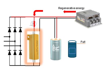
Figure 2:
The shunt resistor dissipates the regenerative energy as heat. This protects the power supply, but we still have heat that must be dissipated. Otherwise, the shunt resistor will overheat and cause a fault (see figure 3). Typically, over-voltage protection will be activated, causing the driver to disengage the motor and stop generating power. In extreme cases, high voltage may damage system components.
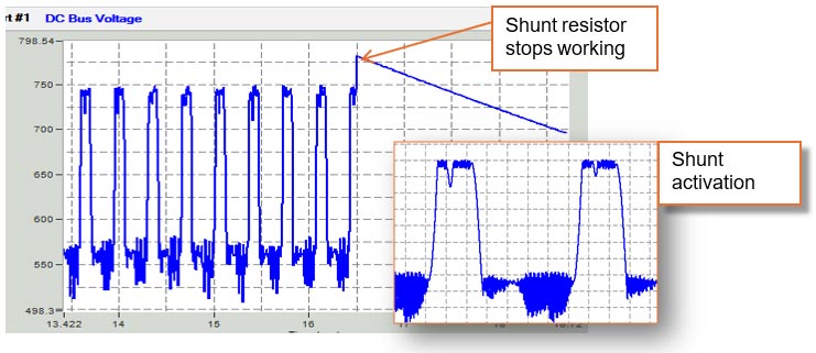
Figure 3: The shunt resistor effectively clamps the voltage at a certain level. When heat builds up beyond a certain threshold, the shunt resistor will fault out (red arrow).
The solution is to increase bus capacitance to enable the bus to absorb more energy before reaching the shunt resistor trimming voltage. This reduces the load on the shunt resistor and lowers the generated heat level.