
Bus capacitance in practice
Consider a pouch-making machine with up to 20 sealing stations. The stations operate simultaneously and continuously with the same profile. During the “release” phase, the axes regenerate power.
Due to the enormous regenerative energy, the machine uses two Elmo TAM100/480VAC power supplies, equipped with a shunt resistor sized to dissipate peak powers of 23 KW. This would be an effective solution if the machine generated these peak powers only occasionally. Unfortunately, with the simultaneous operation of the sealing stations, the shunt resistors were activated several times per second. As a result, they stopped working after a few minutes of operation, resulting in an immediate over-voltage condition that caused the machine to fall out.
Sampling the bus voltage during operation demonstrates the shunt resistor’s high-duty cycle (see figure 4). The DC bus voltage rises to 750 VDC on every cycle for approximately 70 ms. Once the bus voltage reaches 750 VDC, which is the shunt trimming voltage, the power supply diverts voltage to the shunt resistor.
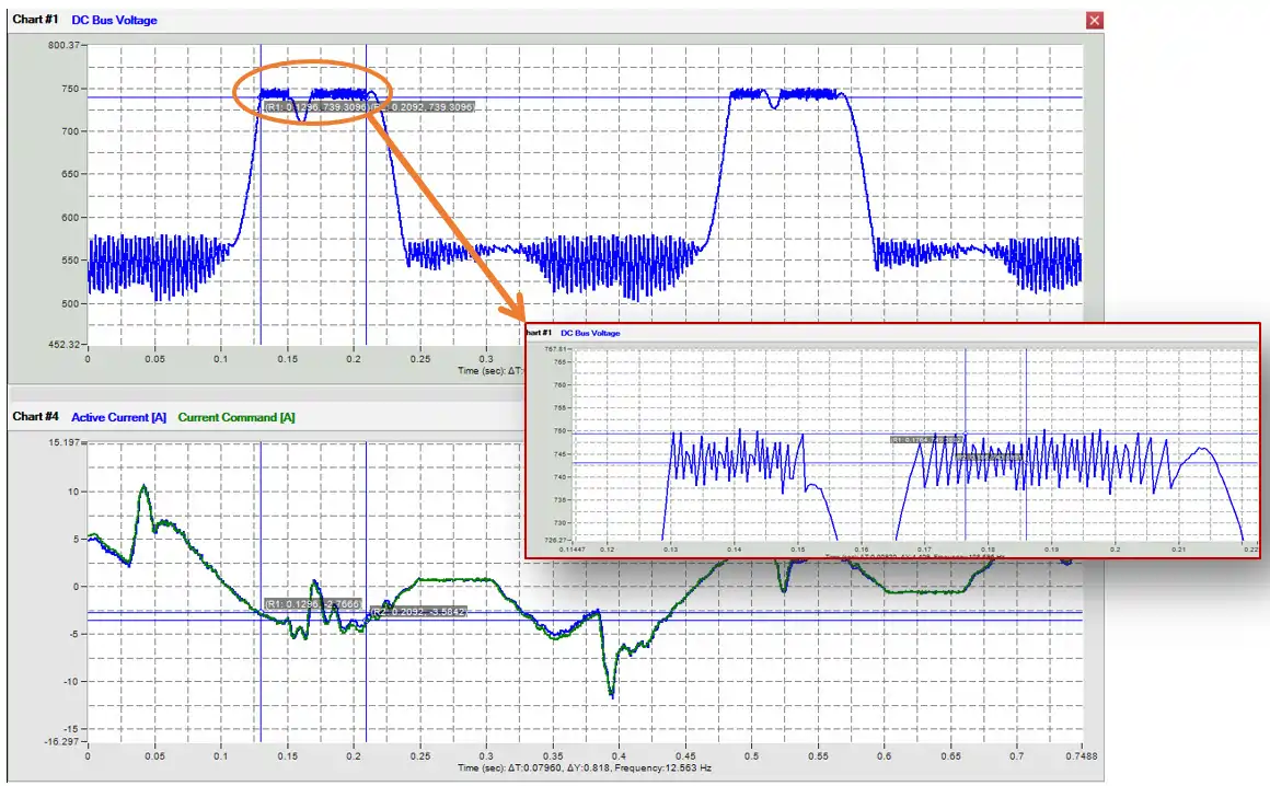
Figure 4: ceiling scene machine pouch sealing machine increases DC bus voltage to 750 V DC every 70 ms, activating the shunt resistor. The buildup from the high duty cycle caused the axes to fault repeatedly, stopping production.
The solution to this problem is to size a capacitor that can capture and store regenerative energy. If we start by calculating the regenerative energy produced by viewing the voltage mean at its peak, we can estimate a 50% activation rate. This means that the shunt resistor only dissipates half of its maximum power (23KW for this model).
(Note: an alternative approach to determining activation rate is to measure the voltage and the reversing current with an external scope and estimate accordingly how much energy is being dissipated.)
On every cycle, the regenerative energy Eregen being dissipated through the shunt resistor is:
Eregen =P*t
Where P is power and t is time. In our case, the dissipated energy is 50% of 23KW over a duration of 0.06 s for a total of approximately 690 J.
Although the shunt resistor provides protection during occasional power spikes, it is not appropriate to deal with continual regeneration. Adding a capacitor bank to the bus to absorb the regenerated energy reduces energy consumption of the machine as a whole while increasing the lifetime of the shunt resistor and reducing downtime. Let’s take a look at sizing.
In order to calculate the extra bus capacitance C required, we will use the expression for capacitor energy, Ecap, which is:
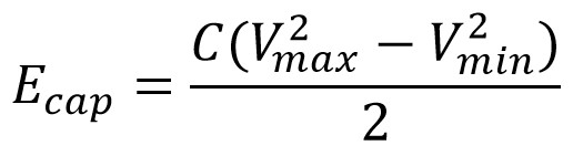
Where Vmax is the maximum allowable voltage (750VDC, in our case) and Vmin is the nominal bus voltage before the regenerative energy (560VDC, in our case).
According to the above, the required capacitance should be:

If we add 5000uF additional capacitance to the system, and it absorbs and stores the additional voltage. The bus voltage never reaches 750 VDC; the shunt resistor is never activated.
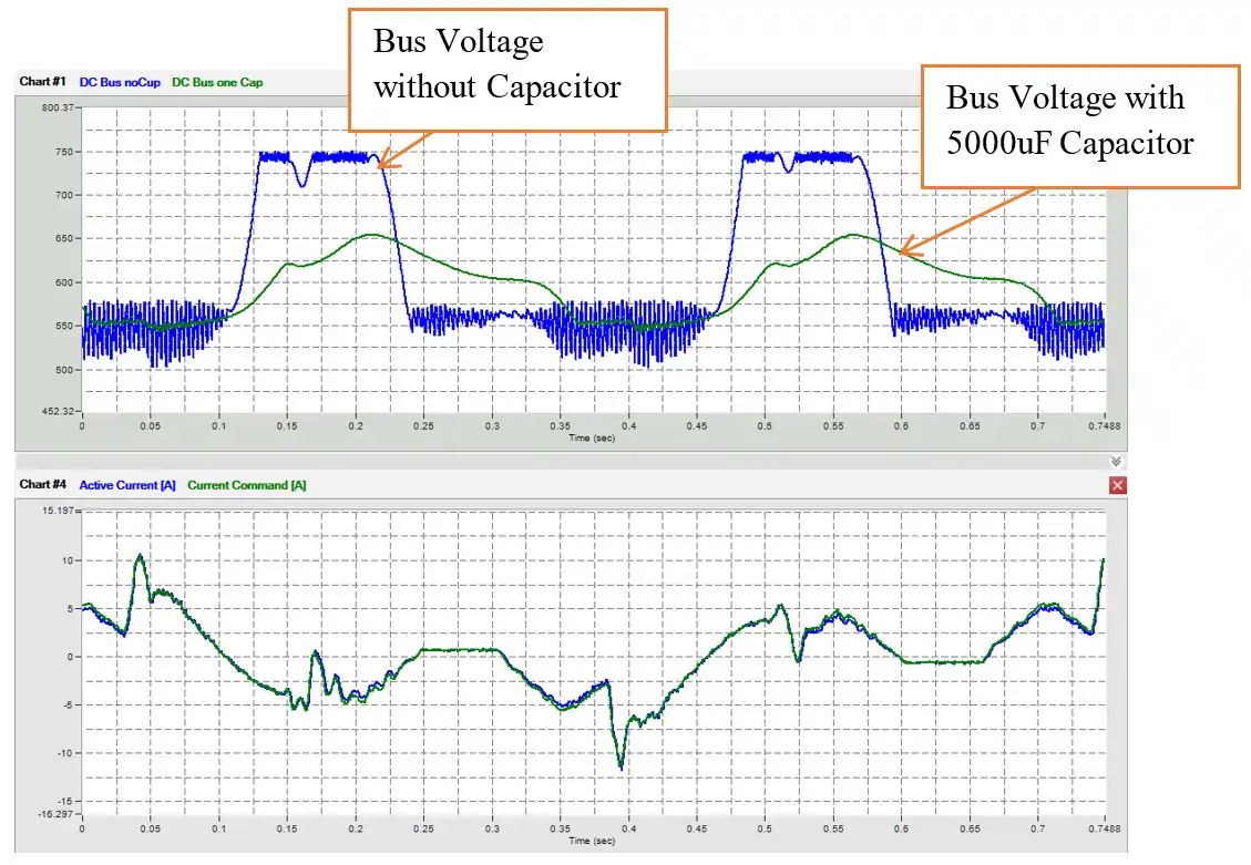
Figure 5: Regenerative energy repeatedly drives the bus voltage of the pouch sealing machine above the threshold (blue line), overheating the shunt resistor and triggering unnecessary nuisance and faults. With the addition of the 5000 µF capacitor bank, the bus voltage (green line) never reaches the threshold.
A shunt resistor prevents the machine from faulting out at high speeds, so the user can run it much faster rates (see figure 7).
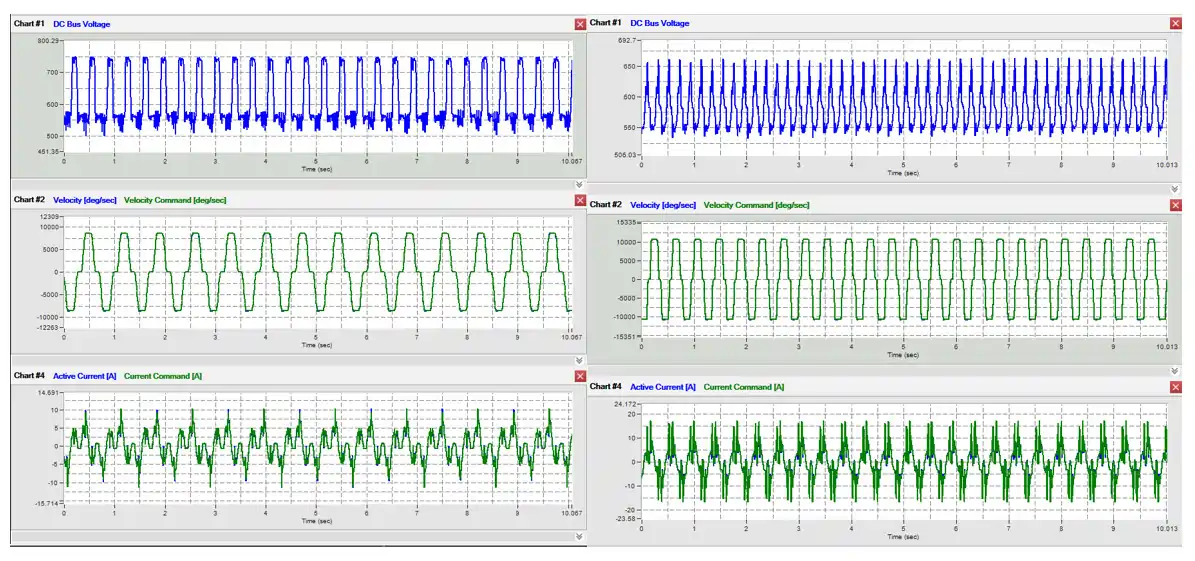
Figure 6: Using the capacitor bank eliminated nuisance faults from the overheated shunt resistor. As a result, it could achieve significantly higher speeds.
Sizing regenerative drives
The linear motors market is constantly growing and brings direct, accurate, high-performance motion systems to more and more applications. Although linear motors can be effective solutions for many cases, they also can introduce challenges. Linear motors are typically equipped with low-friction rails. Minimal friction is good for precision positioning but most of the kinetic energy flows back to the power supply, and stress on the shunt resistor is high. Here, a regenerative drive can help, but only if it is properly sized.
Consider a linear axis with a 40kg payload that accelerates and decelerates in a triangle profile. For the duration of the machine’s operation, it repeats the sequence for 500ms and then rests for 500ms. The key operating parameters are:
| Travel: | 1m |
| Acceleration: | 6m/s² |
| Deceleration: | 6m/s² |
| Mass: | 40kg |
| Cycle Period: | 1.23s |
| Deceleration time: | 0.365s |
| Bus Voltage: | 220VAC |
| Kt | 57.2N/A |
| Resistance | 3.4W |
We start by calculating the regenerative energy produced. Assuming zero frictional force, E deceleration is given by:

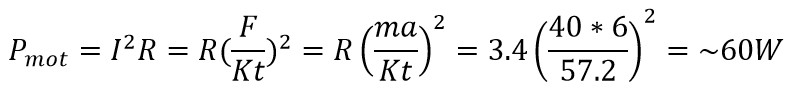
We can calculate reduced power output Pmot from the motor as a result of copper loss using:
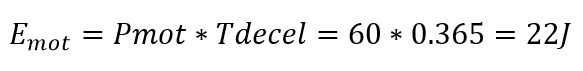
And the corresponding energy loss Emot is:
We can express regenerative energy Eregeneration as:

This axis will regenerate 74j every cycle, meaning every 1.23s
The bus voltage is 311 VDC after rectification. Elmo has two regenerative drives that could potentially work:
- G-OBO10/230FE
- charge voltage level: 380 VDC
- total energy storage: ~57.7J
- capacitor size: 800uF
- G-OBO10/480FE
- charge voltage level: 750 VDC
- total energy storage: ~56.2J
- capacitor size: 200uF
Explanation:
Both drives are the same physical size and have similar energy storage capacity. At first consideration, the G-OBO10/230FE seems like a good fit. Its charge voltage level is high enough to exceed the level of the system by a comfortable margin. It also has sufficient energy storage capabilities. Ultimately, however, it was not the best choice. The G-OBO10/480FE was finally chosen due to its better energy absorption when running at 220VAC
Even though G-OBO10/480FE capacitor absorbs 46.6 J it is still insufficient to store all of the regenerative energy, as the axis regenerates 74 J every cycle. We still need to dissipate ~28J every cycle.
To determine what size of shunt resistor we need to know the power generated by the system and the average power can be calculated accordingly:
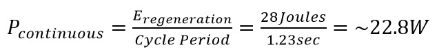
This continuous power can be dissipated through the driver’s built-shunt resistor, which has a maximum allowed continuous power.
Conclusions
When working with large capacitors, users should take key precautions. A large capacitor increases the inrush current at power-up, so choosing the machine’s circuit breaker must be taken very seriously and carefully. At Elmo, we recommend circuit breaker type C. Dangerous power can still exist on the bus voltage even after shutdown due to a charge on the capacitor. Users must protect the hotlines and ensure proper discharge of the capacitor at power-off.
Although increasing bus capacitance can be very effective when properly sized and applied, it is not the perfect solution for all applications. It’s all a matter of numbers. If the regenerative energy is too large it is not practical to solve by a capacitor and other solutions should be used. It is most effective for production machines with an ongoing cycle of fast acceleration and decelerations such as packaging machines, AOI machines, etc.