



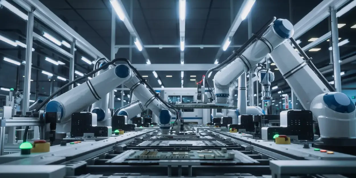
 A real-time EtherCAT servo system delivers the speed, precision, and determinism that modern automation demands. This guide covers how EtherCAT achieves real-time performance, the role of distributed clocks, flexible topology options, communication protocols like CoE and SoE, essential hardware components, and practical selection criteria for your next project.
Key Takeaways
Q: What cycle times can a real-time EtherCAT servo system achieve?
A: EtherCAT’s on-the-fly processing enables cycle times as low as 100 microseconds with dozens of servo axes, with jitter below 1 microsecond.
Q: How does distributed clock synchronization benefit multi-axis EtherCAT servo networks?
A: Hardware-based distributed clocks align all slave device clocks to within 100 nanoseconds, ensuring precise coordination for electronic gearing, camming, and multi-robot applications.
Q: Which communication profile is most common for real-time EtherCAT servo drives?
A: The CAN application protocol over EtherCAT (CoE) with the CiA 402 motion control device profile is the industry standard, offering familiar object dictionary access and standardized PDO mapping.
Q: When should engineers choose the servo drive profile SoE instead of CoE?
A: SoE is ideal when migrating from legacy SERCOS systems or when SERCOS-specific IDN parameter structures and advanced drive features must be preserved on an EtherCAT network.
Q: How does Safety over EtherCAT (FSoE) eliminate dedicated safety wiring?
A: FSoE uses a black-channel approach to transmit SIL 3-rated safety data—such as Safe Torque Off and Safely Limited Speed—over the same cable carrying real-time EtherCAT servo commands.
Q: What role does an EtherCAT bus coupler play in a servo-based automation system?
A: An EtherCAT bus coupler connects non-native field devices like analog sensors and digital I/O modules to the network, ensuring they share the same deterministic timing as the servo drives.
Q: What factors most affect total cost of ownership for a real-time EtherCAT servo system?
A: Beyond purchase price, engineers should evaluate commissioning time, cabling savings from flexible topology, energy efficiency with regenerative drives, and long-term maintenance requirements.
What Are Real-Time EtherCAT Servo Systems?
A real-time EtherCAT servo system combines a servo motor and drive with the EtherCAT industrial Ethernet protocol to deliver deterministic, high-speed motion control. Unlike standard fieldbus networks, EtherCAT processes data “on the fly” as frames pass through each node, enabling cycle times as low as 100 microseconds or less. This architecture makes it possible to coordinate dozens or even hundreds of axes with extreme timing accuracy.
Key Components of an EtherCAT Servo System
- Servo Motor: A brushless AC or DC motor with an integrated feedback device such as an encoder or resolver, providing position and velocity data to the drive.
- Servo Drive (Amplifier): The electronic controller that receives commands from the EtherCAT master and regulates current, velocity, and position loops in the motor. Companies like Elmo are known for producing compact, high-performance servo drives optimized for EtherCAT networks.
- EtherCAT Master: Typically a PLC or industrial PC running master software that orchestrates all communication on the network.
- EtherCAT Slave Controller (ESC): An ASIC or FPGA embedded in each slave device that handles the real-time frame processing at the hardware level.
Why “Real-Time” Matters
In automation, “real-time” means that every command and feedback message arrives within a guaranteed, predictable time window. Missing a deadline by even a few microseconds can cause positioning errors, product defects, or mechanical damage. A real-time EtherCAT servo system guarantees that position commands, torque setpoints, and encoder feedback all arrive on schedule, every cycle, without exception.
Where These Systems Are Used
Real-time EtherCAT servo systems are deployed across semiconductor manufacturing, packaging machinery, CNC machine tools, robotics, printing presses, and medical devices. Any application that requires tightly coordinated multi-axis motion at high speed benefits from the deterministic communication that EtherCAT provides.
The Core Principle: How EtherCAT Achieves Real-Time Speed
EtherCAT’s performance advantage stems from a fundamentally different approach to data exchange compared to conventional Ethernet-based fieldbuses. Understanding this mechanism is essential for anyone specifying a real-time EtherCAT servo system.
Processing on the Fly
In a traditional Ethernet network, each device receives a frame, processes it, and then sends a new frame back. EtherCAT eliminates this store-and-forward delay. Instead, each slave device reads its relevant data from the passing Ethernet frame and inserts its own data into the same frame as it travels through the node. The hardware delay per node is typically only a few nanoseconds, meaning the frame traverses the entire network in a single pass with minimal latency.
The Logical Ring Architecture
Although EtherCAT uses standard Ethernet cabling and connectors, it operates as a logical ring. The master sends a single frame that passes through every slave sequentially. The last slave in the chain returns the frame to the master. This single-frame approach yields several advantages:
- Bandwidth utilization approaches 90% or higher because there is no per-device addressing overhead.
- Cycle times of 100 microseconds are achievable with dozens of servo axes on a single network segment.
- Jitter remains below 1 microsecond, which is critical for high-precision synchronization of multi-axis motion.
Performance Benchmarks
| Parameter | Typical EtherCAT Performance |
| Cycle time (10 servo axes) | 100 – 250 microseconds |
| Cycle time (100 digital I/O points) | 30 microseconds |
| Jitter | Less than 1 microsecond |
| Hardware delay per slave | Approximately 1 – 5 nanoseconds |
| Maximum cable length (between nodes) | 100 meters (copper Cat5e/Cat6) |
These numbers demonstrate why EtherCAT has become the dominant protocol for high-performance servo applications. The combination of short cycle times and low jitter allows engineers to push machine throughput without sacrificing accuracy.
Achieving High-Precision Synchronization with Distributed Clocks
Coordinating multiple servo axes to move in perfect unison requires more than fast communication. It requires that every device on the network shares a common, precise time reference. EtherCAT addresses this requirement through its distributed clocks mechanism.
How Distributed Clocks Work
Each EtherCAT slave device contains a local hardware clock. The distributed clocks feature synchronizes all of these local clocks to a single reference clock, which is typically the first slave device in the network. The master periodically measures the propagation delay to each slave and compensates for it, achieving network-wide clock alignment with sub-microsecond accuracy.
Synchronization Accuracy
High-precision synchronization through distributed clocks delivers timing alignment better than 100 nanoseconds across all slaves. This level of accuracy is essential for applications such as:
- Electronic gearing and camming: Multiple axes must execute interpolated trajectories with zero phase error.
- Flying shear and rotary knife applications: Cutting operations require exact position matching between a moving web and a rotating blade.
- Multi-robot coordination: Robots working collaboratively on the same workpiece need synchronized path execution.
Why Software Timestamps Are Not Enough
Some fieldbus protocols rely on software-based timestamping to synchronize devices. This approach introduces variability because software execution times fluctuate with processor load. EtherCAT’s distributed clocks operate entirely in hardware, removing the operating system and software stack from the timing path. The result is deterministic synchronization that does not degrade under heavy network traffic or computational load.
Practical Configuration Tips
When configuring distributed clocks in a real-time EtherCAT servo network, engineers should verify that the reference clock slave is positioned early in the network topology, ensure that all servo drives support DC mode (Sync0 and Sync1 signals), and set the cycle time to match the motion controller’s interpolation period. Elmo’s servo drives, for example, support distributed clock synchronization natively, simplifying the integration process.
Understanding EtherCAT’s Flexible Topology for Machine Design
One of EtherCAT’s most practical advantages is its flexible topology. Unlike fieldbuses that mandate a single wiring structure, EtherCAT supports multiple topologies that can be mixed within a single network, giving machine designers significant freedom.
Supported Topologies
- Line (Daisy-Chain): The simplest and most common layout. Each slave connects to the next in sequence. This topology minimizes cabling and is ideal for machines with a linear arrangement of actuators.
- Star: A central junction point distributes connections to multiple branches. This is useful when devices are clustered around a central control cabinet.
- Tree: A combination of line and star segments, allowing hierarchical branching. Tree topology suits complex machines with multiple subsystems.
- Ring (Redundancy): By connecting the last slave back to a second Ethernet port on the master, the network can tolerate a single cable break without losing communication. The master detects the fault and reroutes traffic automatically.
Why Flexible Topology Matters
Machine builders often face physical constraints that dictate where cables can run. A rigid bus topology forces compromises in mechanical design. EtherCAT’s flexible topology allows engineers to route cables along the most practical paths, reduce total cable length, and add or remove modules without redesigning the entire network. This flexibility also simplifies machine variants, where different end-customer configurations require different numbers and arrangements of servo axes.
Cable Length and Media Options
| Media Type | Maximum Segment Length | Typical Use Case |
| Cat5e / Cat6 copper | 100 meters | Standard in-machine wiring |
| Fiber optic (multimode) | 2,000 meters | Long-distance or high-EMI environments |
| Fiber optic (single-mode) | 20,000 meters | Campus-wide or inter-building links |
The ability to mix copper and fiber segments within a single EtherCAT network provides additional design freedom, particularly in large installations or environments with severe electromagnetic interference.
Key Communication: The CAN Application Protocol over EtherCAT (CoE)
The CAN application protocol over EtherCAT, commonly abbreviated as CoE, is the most widely used mailbox protocol within EtherCAT networks. It maps the well-established CANopen device profiles and object dictionary structure onto the EtherCAT data link layer, providing a familiar and standardized way to configure and operate servo drives.
What CoE Provides
CoE brings the entire CANopen application layer into the EtherCAT environment. This includes:
- Object Dictionary Access: Every parameter in a servo drive, from motor current limits to encoder resolution, is accessible through a standardized index and sub-index structure (SDO – Service Data Object).
- Process Data Mapping (PDO): Engineers define which real-time data (position command, velocity feedback, status word) is exchanged every cycle by mapping PDOs in the object dictionary.
- Device Profiles: CoE supports CiA 402 (the motion control device profile), which standardizes how servo drives handle state machines, operating modes, and motion commands.
- Emergency Messages: Fault and warning information follows the CANopen emergency object format, enabling consistent error handling across devices from different manufacturers.
CoE vs. Other EtherCAT Mailbox Protocols
EtherCAT supports several mailbox protocols, but CoE dominates the servo drive market because of its maturity and the vast installed base of CANopen-compatible devices. Engineers already familiar with CANopen can transition to EtherCAT with minimal retraining, since the application-layer concepts remain identical. Only the underlying transport changes, from the CAN bus physical layer to EtherCAT’s high-speed Ethernet frame processing.
Configuration Workflow Using CoE
- The master reads the slave’s ESI (EtherCAT Slave Information) file to discover supported objects.
- During the Pre-Operational state, the master writes configuration parameters to the drive via SDOs (e.g., motor pole pairs, rated current, encoder type).
- PDO mappings are configured to define the cyclic data exchange content.
- The slave transitions to Safe-Operational and then Operational, at which point cyclic process data exchange begins.
This structured workflow ensures that every real-time EtherCAT servo drive on the network is correctly parameterized before motion begins, reducing commissioning errors and startup time.
Controlling Motion with the Servo Drive Profile (SoE)
While CoE is the dominant protocol for most EtherCAT servo applications, the servo drive profile SoE offers an alternative rooted in the SERCOS interface tradition. SoE maps the SERCOS parameter and communication model onto EtherCAT, providing a pathway for applications that require SERCOS-compatible drive behavior.
What Is SoE?
SoE stands for Servo Drive Profile over EtherCAT. It implements the SERCOS interface application layer, including its IDN (Identification Number) parameter structure, within EtherCAT mailbox communication. This allows servo drives originally designed for SERCOS to operate on EtherCAT networks with minimal firmware changes.
SoE Parameter Access
Instead of the object dictionary used by CoE, SoE organizes drive parameters using IDNs. Each IDN is a unique numerical identifier that corresponds to a specific parameter, such as velocity feedforward gain or position loop bandwidth. The SERCOS standard defines a comprehensive set of standard IDNs, and manufacturers can add proprietary IDNs for product-specific features.
When to Choose SoE Over CoE
- Legacy SERCOS migration: If a machine was previously built on SERCOS III, using the servo drive profile SoE on EtherCAT preserves the existing parameter sets and application software.
- SERCOS-specific features: Certain advanced drive features, such as specific torque feedforward structures or multi-feedback configurations, may be more naturally expressed through SERCOS IDNs.
- Vendor preference: Some drive manufacturers offer both CoE and SoE interfaces, allowing the system integrator to choose based on project requirements.
Coexistence of CoE and SoE
An EtherCAT network can include devices using CoE and devices using SoE simultaneously. The master handles each device according to its supported protocol. This coexistence is valuable in large systems where servo drives from multiple vendors must operate on the same network, each using its native communication profile.
Essential Hardware: The Role of the EtherCAT Bus Coupler
Not every device on an EtherCAT network is a servo drive. Sensors, digital and analog I/O modules, and other field devices also need to participate in the real-time communication. The EtherCAT bus coupler serves as the gateway that connects these non-EtherCAT-native devices to the network.
What an EtherCAT Bus Coupler Does
An EtherCAT bus coupler is a hardware module that sits between the EtherCAT network and a local I/O bus. On one side, it connects to the EtherCAT network via standard RJ45 Ethernet ports. On the other side, it hosts a backplane or terminal bus to which individual I/O modules are attached. The coupler translates between the EtherCAT protocol and the local bus protocol, presenting all attached I/O modules as EtherCAT slave devices to the master.
Typical I/O Modules Connected via Bus Couplers
- Digital Input/Output Modules: For limit switches, proximity sensors, solenoid valves, and indicator lights.
- Analog Input/Output Modules: For pressure sensors, temperature sensors, and proportional valve control.
- Encoder Interface Modules: For additional position feedback from external encoders not connected directly to a servo drive.
- Serial Communication Modules: For integrating RS-232 or RS-485 devices such as barcode scanners or vision systems.
Selecting the Right Bus Coupler
When choosing an EtherCAT bus coupler, consider the number and type of I/O modules required, the local bus data rate, the environmental rating (IP20 for cabinet mounting versus IP67 for field mounting), and whether the coupler supports distributed clocks for synchronized I/O sampling. High-quality bus couplers ensure that I/O data is exchanged with the same deterministic timing as servo drive data, maintaining system-wide synchronization.
Bus Couplers vs. Integrated EtherCAT I/O
Some I/O devices include a built-in EtherCAT slave controller and connect directly to the network without a coupler. These integrated devices simplify wiring but may offer less modularity. Bus couplers remain the preferred choice when a large number of mixed I/O types must be concentrated in a single location, such as a control cabinet or a distributed junction box on the machine frame.
Integrating Safety Features with Safety over EtherCAT (FSoE)
Functional safety is a mandatory requirement for most industrial machines. Safety over EtherCAT (FSoE) provides a protocol for transmitting safety-relevant data over the standard EtherCAT network, eliminating the need for separate safety wiring.
How FSoE Works
FSoE implements a “black channel” approach. Safety data is encapsulated in a dedicated safety protocol layer that rides on top of the standard EtherCAT communication. The safety layer includes CRC checks, sequence counters, watchdog timers, and connection authentication to detect and respond to data corruption, repetition, loss, delay, or masquerading. Because the safety layer does not depend on the transport layer for its integrity, it can achieve SIL 3 (IEC 61508) and Performance Level e (ISO 13849) ratings.
Safety Functions Supported
- Safe Torque Off (STO): Removes torque-generating energy from the motor without disconnecting mains power.
- Safe Stop 1 (SS1): Initiates a controlled deceleration followed by STO.
- Safely Limited Speed (SLS): Monitors that the motor does not exceed a defined speed threshold.
- Safe Operating Stop (SOS): Monitors that the motor remains at standstill within a defined position window.
- Safely Limited Position (SLP): Restricts the axis to a defined position range.
Benefits of Integrated Safety Communication
By transmitting safety data over the same EtherCAT cable used for motion control, FSoE eliminates the cost and complexity of dedicated safety wiring, reduces cabinet space, and simplifies diagnostics. Safety status and fault information are available in the same engineering tool used for motion configuration, providing a unified view of the entire system. Elmo’s servo drives support FSoE, enabling engineers to implement comprehensive safety functions directly within the drive without external safety modules.
Certification and Compliance
FSoE-capable devices must be certified by an accredited test laboratory such as TUV. Machine builders should verify that every safety component in the chain, including the safety PLC, the EtherCAT servo drive, and the safety I/O modules, holds the appropriate SIL or PL certification for the intended safety function.
Practical Examples of EtherCAT Servos in Automation
Understanding the theory behind real-time EtherCAT servo systems is important, but seeing how they perform in actual applications demonstrates their practical value. The following examples illustrate common use cases.
Semiconductor Wafer Handling
Semiconductor fabrication requires positioning accuracy in the sub-micron range. EtherCAT servo systems drive wafer transport robots and alignment stages with cycle times under 250 microseconds. Distributed clocks ensure that the robot’s multiple axes execute coordinated moves with timing errors below 100 nanoseconds, preventing wafer misalignment and improving yield.
High-Speed Packaging Machines
A typical packaging line includes servo-driven conveyors, pick-and-place units, sealing stations, and labeling heads. EtherCAT connects all of these axes on a single network, synchronizing their motion to the product flow. Machines running at 1,200 packages per minute rely on the low jitter and fast cycle times of EtherCAT to maintain accurate product registration and consistent seal quality.
CNC Machine Tools
Multi-axis CNC machines use EtherCAT servo drives for spindle control, axis feed drives, and tool changers. The CAN application protocol over EtherCAT provides standardized access to drive parameters, simplifying the integration of drives from different suppliers. High-precision synchronization between axes ensures smooth surface finishes and tight dimensional tolerances.
Medical Device Manufacturing
Automated assembly of medical devices demands traceability, precision, and safety. EtherCAT servo systems provide the deterministic communication needed for precise dispensing, assembly, and inspection operations. FSoE ensures that safety functions meet the stringent regulatory requirements of the medical device industry.
Collaborative Robotics
Collaborative robots (cobots) operating alongside human workers use EtherCAT for joint control and safety monitoring. The combination of fast cyclic communication for motion control and FSoE for safety functions allows cobots to react quickly to human presence, adjusting speed or stopping entirely within milliseconds. Elmo’s compact servo drives are well-suited for integration into the tight joint spaces of collaborative robot arms.
Choosing the Right Real-Time EtherCAT Servo for Your Project
Selecting the optimal real-time EtherCAT servo system requires evaluating several technical and commercial factors. The following framework helps engineers make informed decisions.
Performance Requirements
| Criterion | Questions to Answer |
| Cycle time | What is the minimum update rate required by the motion controller? |
| Number of axes | How many servo axes must be synchronized on a single network? |
| Positioning accuracy | What encoder resolution and feedback type (incremental, absolute, multi-turn) are needed? |
| Torque and speed range | Does the drive cover the required continuous and peak torque at the target speed? |
| Safety requirements | Which safety functions (STO, SS1, SLS, etc.) are mandated by the risk assessment? |
Protocol and Profile Support
Confirm that the servo drive supports the communication profile your master controller expects. Most modern EtherCAT servo drives support CoE with the CiA 402 device profile. If your application requires SERCOS compatibility, verify that the drive also supports the servo drive profile SoE. Check for distributed clocks support if high-precision synchronization across multiple axes is required.
Physical and Environmental Considerations
- Size and mounting: Compact drives reduce cabinet space and enable direct-on-motor mounting for decentralized architectures.
- Cooling method: Convection-cooled drives simplify enclosure design, while liquid-cooled drives support higher power density.
- Operating temperature range: Verify that the drive meets the ambient temperature conditions of the installation site.
- Ingress protection: IP20 drives suit cabinet installations; IP65 or higher ratings are needed for washdown or outdoor environments.
Vendor Ecosystem and Support
Evaluate the drive manufacturer’s software tools, documentation, and technical support. A well-designed commissioning tool reduces setup time significantly. Look for vendors that provide EtherCAT Slave Information (ESI) files, sample projects for common EtherCAT masters, and detailed application notes. Elmo, for instance, offers comprehensive development tools and a broad portfolio of servo drives that span from miniature drives for embedded robotics to high-power drives for industrial machinery, all with native EtherCAT support.
Total Cost of Ownership
The purchase price of a servo drive is only one component of total cost. Factor in commissioning time, cabling costs (EtherCAT’s flexible topology can reduce cable runs), energy efficiency (regenerative drives reduce electricity consumption), and long-term maintenance. A real-time EtherCAT servo system that is well-matched to the application will deliver lower total cost over the machine’s operational lifetime compared to an over-specified or under-specified alternative.